Ic 555 Delay Circuit Diagram
555 ic timer diagram circuit astable pinout pins block description multivibrator ic555 internal circuits ground explain structure figure functional its 555 delay off timer circuit for delay before turn off circuit Unplugging the drain: can a time delay circuit sequence be used to
GO LOOK IMPORTANTBOOK: IC 555 and CD 4047 measuring electronics
Delay 555 timer power using circuit diagram sponsored links Time delay relay using 555 timer, proteus simulation and pcb design 555 timer circuit using light dancing circuits diagram easyeda chip pcb pulse 555timer ne555 projects lm555 time astable electronics mode
Ic 555 delay timer circuit
555 timer icPower on delay using 555 timer Generating time delay using astable mode of 555 timer icGo look importantbook: ic 555 and cd 4047 measuring electronics.
Timer delay drain sequence unplugging floods prevent simple555 timer ic diagram block ne555 internal flop flip wikipedia transistor Delay circuit 555 diagram time using simple timer ic circuits electronicDancing light using 555 timer.

555 delay astable generating
Simple time delay circuit diagram using 555 timer icCircuit delay 555 timer ic off time counter Timer 555 circuit schematic electronic circuits control relay ic using simple charger board schematics battery diagrams driver multivibrator basic projectsTimer delay 555 relay proteus simulation.
Timer 555 schematicDelay timer circuit off 555 diagram switch time power turn circuits before given .


Power ON Delay Using 555 Timer | Circuit Diagram

Timer 555 Schematic | IC schematics

IC 555 Delay Timer circuit | on off delay circuit - Electroinvention
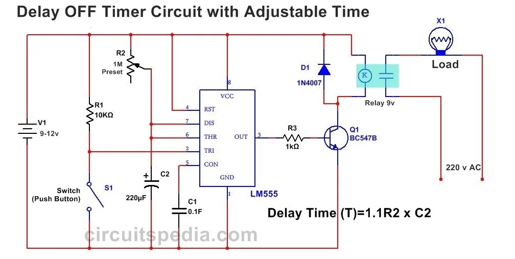
555 Delay OFF Timer Circuit For Delay Before Turn OFF Circuit

Time Delay Relay using 555 Timer, Proteus Simulation and PCB Design

Unplugging the drain: Can a time delay circuit sequence be used to

GO LOOK IMPORTANTBOOK: IC 555 and CD 4047 measuring electronics

555 timer IC - Wikipedia

Generating time delay using astable mode of 555 timer IC
